
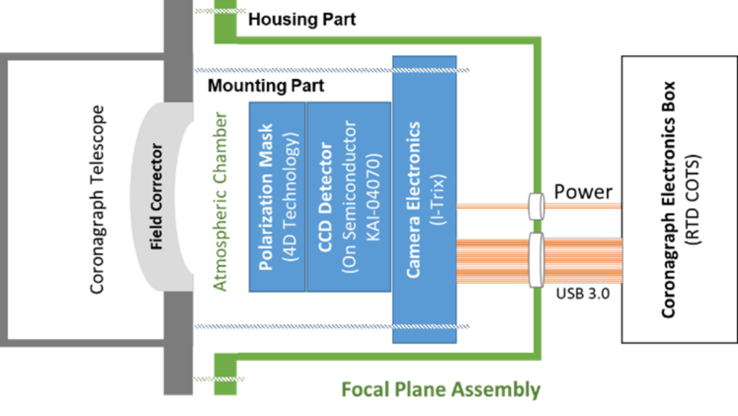
Focal Plan Assembly
In order to measure density, temperature, and velocity of the solar corona, we develop a pixelated polarization camera with KAI-04070 CCD sensor.
The pixelated polarization camera has a micro polarizer array with four different polarization angles (0, 45, 90, and 135 degrees) on top of pixels.
It can make us capture polarized light at each of four different angles simultaneously in one image.
It is similar to the principle that a color camera collects RGB information using a Bayer filter which is a color filter array with four different color filters: red, green, blue, and green.
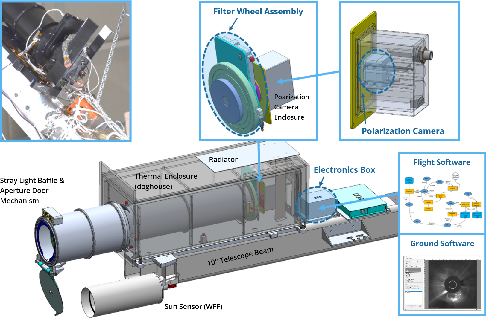
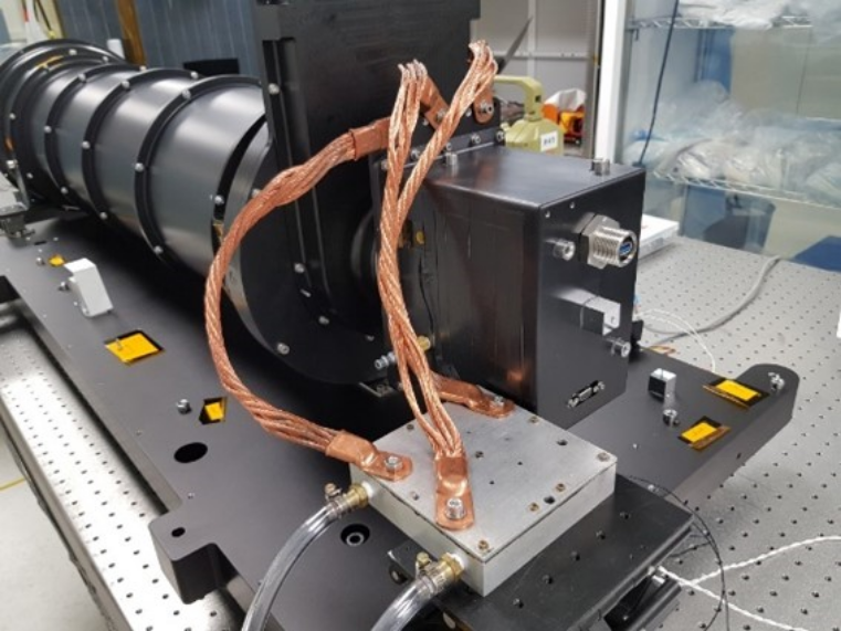
The focal plane assembly of the BITSE is composed of a pressure chamber, and a polarization camera.
The pixelated polarization mask mounted on a CCD sensor is not compatible with a vacuum condition and its operation temperature is not wide enough because of its bonding material.
In order to protect from vacuum condition, we design a pressure chamber with 1 atm.
And we design a radiator to dissipate heats and a heater to protect it from too cold temperature.
We control the heater by monitoring the temperature of the CCD sensor.
It is able to keep the temperature of the CCD sensor and the polarization mask at 10 degrees in Celsius.
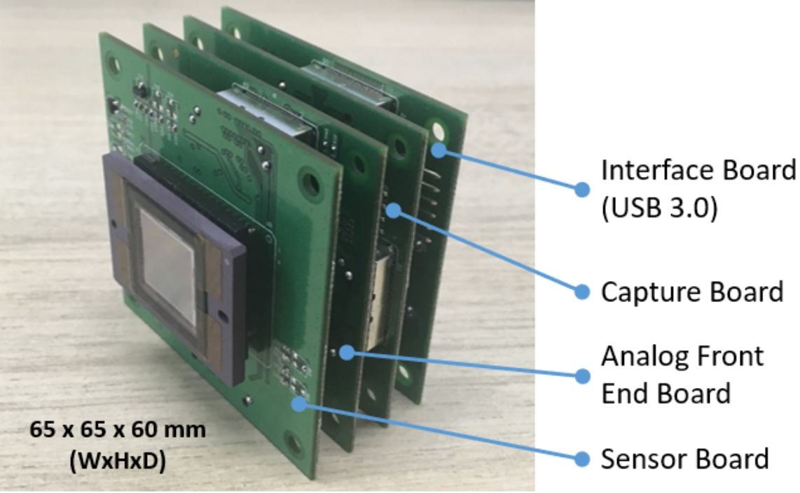
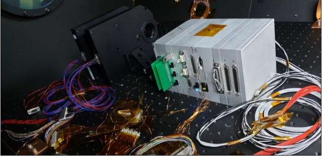
The camera electronics is composed of four electronics boards; a sensor board, an analog front-end (AFE) board, a capture board, and an interface board. The sensor board has a socket for the KAI-04070 CCD sensor. The AFE board is a front-end analog-to-digital converter (ADC). It uses AD9978 of Analog Devices which is 14-bit CCD signal processor for high speed digital camera applications. The capture board captures an image signal from AFE board and transfers to the interface board. It has Xilinx ARTIX 7 (xc7a50T) as a Field-Programmable Gate Array (FPGA). The camera interface provides USB 3.0 interface for the fast image transfer using Cypress FX3 (CYUSB301X). The physical size of the integrated electronics is 65 x 65 x 60 mm in width, height and depth.
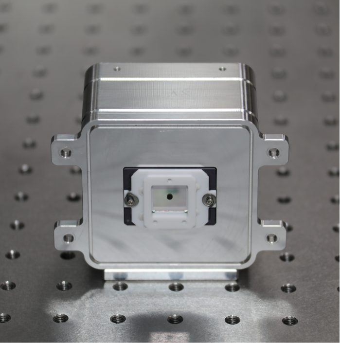
We design a housing considering thermal dissipation and mounting to the coronagraph. It has three separated enclosures. The front enclosure adapts the sensor board, and a thermal plate attaching backside of the CCD sensor. The middle enclosure holds both the AFE board and a capture board. And the back enclosure adapts an interface board and a thermal plate. It holds a power connector and a USB connector also. When it is completely assembled, its dimensions are 77 x 77 x 51.30 mm in width, height, and depth, excepting the bolting structure that is extended to both sides.
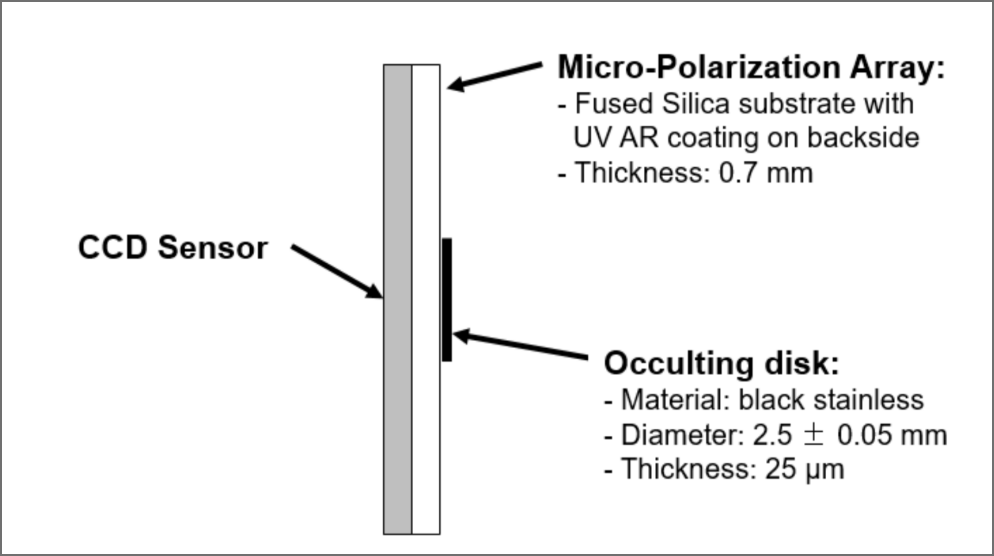
The polarization camera uses the KAI-04070 CCD sensor of On Semiconductor. The sensor is interline CCD type which has higher data transfer rate than other types. Its active pixel resolution is 2048 x 2048. Its pixel size is 7.4 x 7.4 um and the sensor size is 15.2 x 15.2 mm. Its dark current doubling temperature is 7 degree for photodiode and 9 degree for Vccd. It has four output channels for data transfer, and its maximum frame rate is 28 fps at 40 MHz which is maximum pixel clock speed. A Micro-Polarization Array (MPA) and an occulting disk are located on the CCD surface of the pixelated polarization camera. 4-D Technology in U.S. has a patent about a pixelated polarization mask. They mounted both of them on the imaging camera what we developed. The pixel size of the CCD is 7.4 x 7.4 um, and the pixel resolution is 2048 x 2048 pixels. A super pixel covers 2 x 2 pixels which are four different polarization angles. Anti-Reflective (AR) coatings are applied to the MPA backside in UV wavelength. The occulting disk is about 3-mm black occulting disk that corresponding to 3 solar radii to block brighter scatter light.
Filter Wheel Assembly
The requirement of the filter wheel assembly (FWA) is as below.
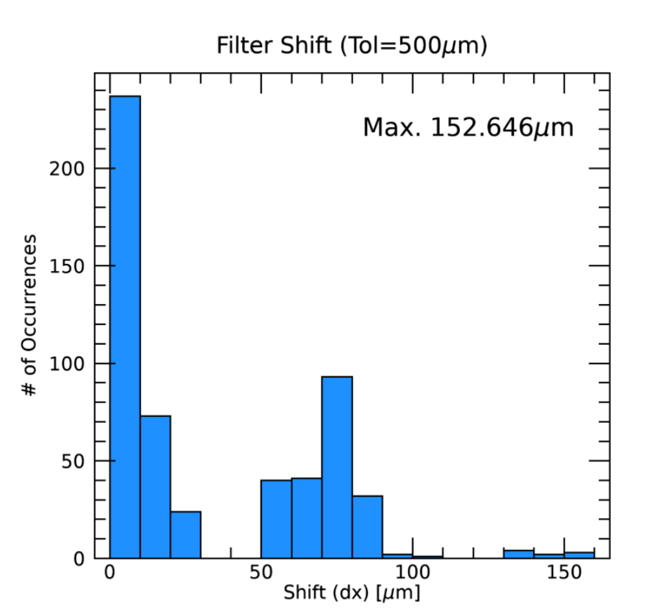
- < 0.5mm Positioning Reliability
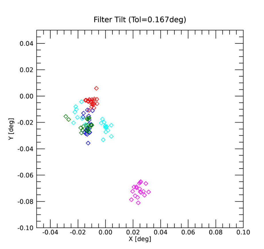
- 9 arcmin Tilt Alignment/Reliability
- Thermal Vacuum compatible
To satisfy the requirement, we used a piezo-motor in the filter wheel.
The Piezo-motor is beneficial on the fast speed and the position accuracy, strong holding-torque, and EMI.
We used the piezo-motor manufactured by 'Piezo-Technology' after modifying some parts.
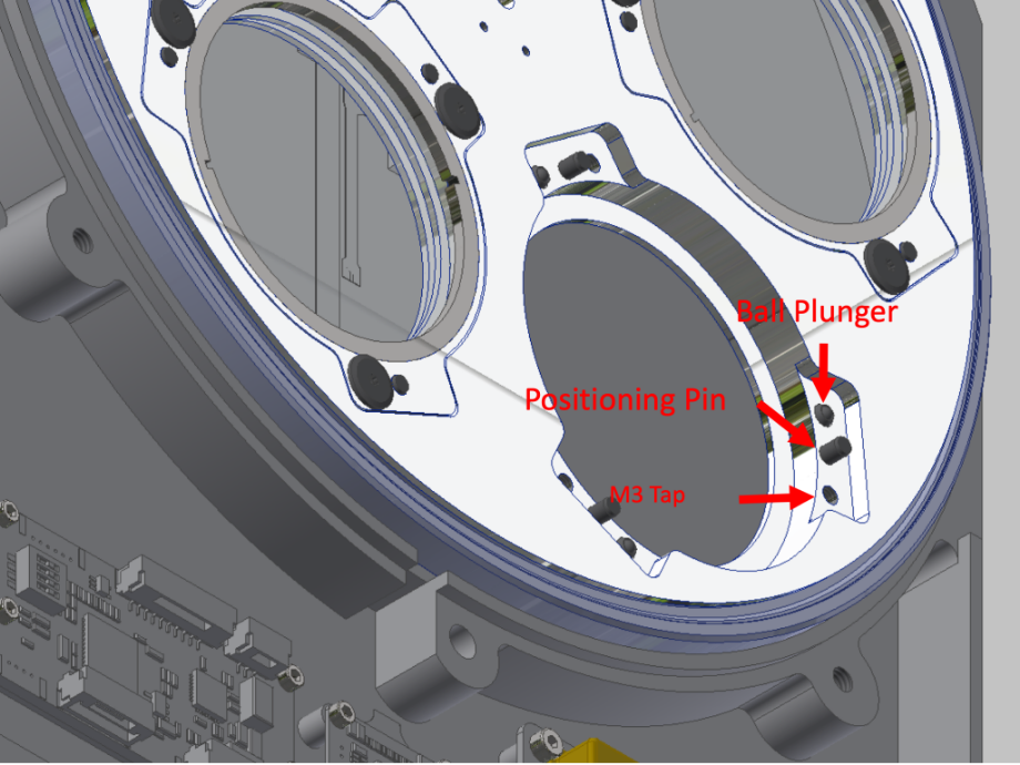 Figure 1. Filter alignment mechanism at each filter module using ball plungers, positioning pins, and screws.
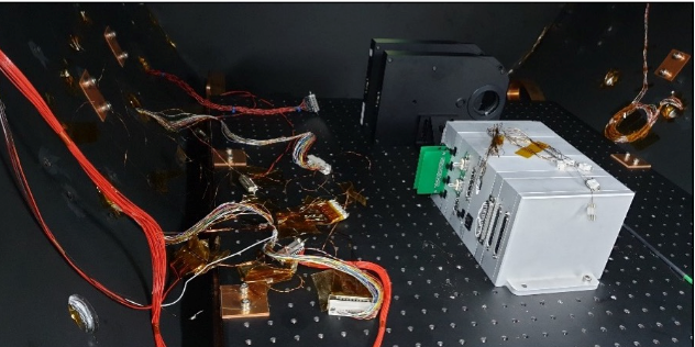
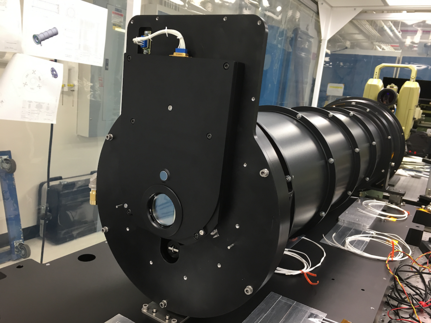
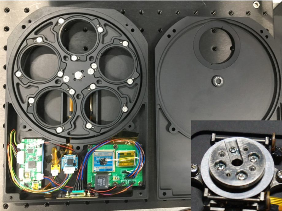 Figure 2. Flight model of the FWA
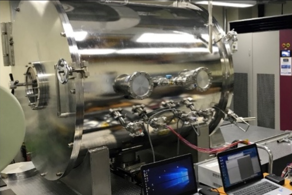
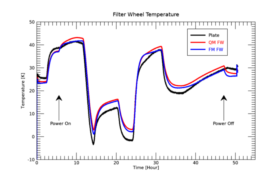
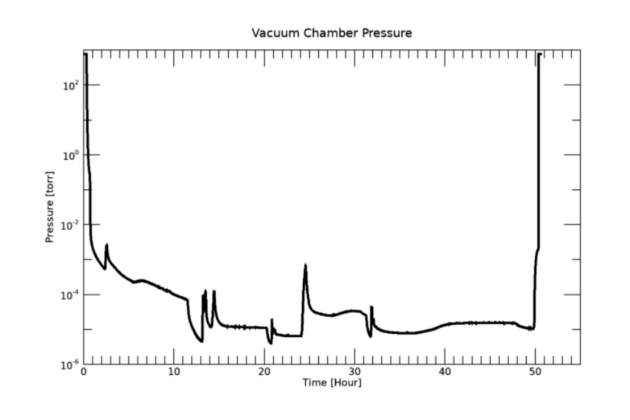
The FWA works well in a temperature range from 0°C to 40°C with high reliability and high positioning accuracy (~0.1deg) with a photo-encoder. We perform more than a dozen tests to varifying the thermal-vacuum compatibility of the filter wheel in the KASI chamber. The FWA was finely tuned from the experiments by changing the lubricant, the rotating speed, the vibration frequency, and the voltage of the piezo-modules.
The manufactured flight models of the FWA were delivered to GSFC, and one of the FM FWA was installed with fine alignment using the reference mirror attached at the center of the FWA.
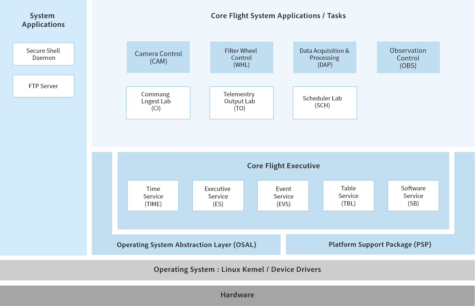
Flight S/W
The BITSE flight software was developed by extending the DICE control software.
The flight software was developed by extending the DICE applications to control the BITSE camera and filter wheel and by creating BITSE applications to communicate with a power supply, a pointing system, and a radio communication system.
KASI completed the BITSE flight software by integrating 9 mission applications and 7 reuse applications for mission operation automation, data processing, system resource management, and software fault tolerance.
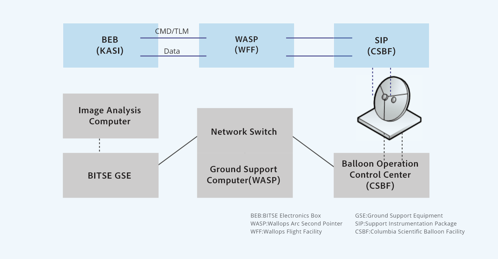
Ground S/W
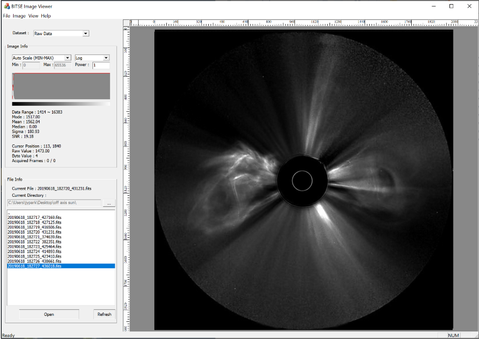
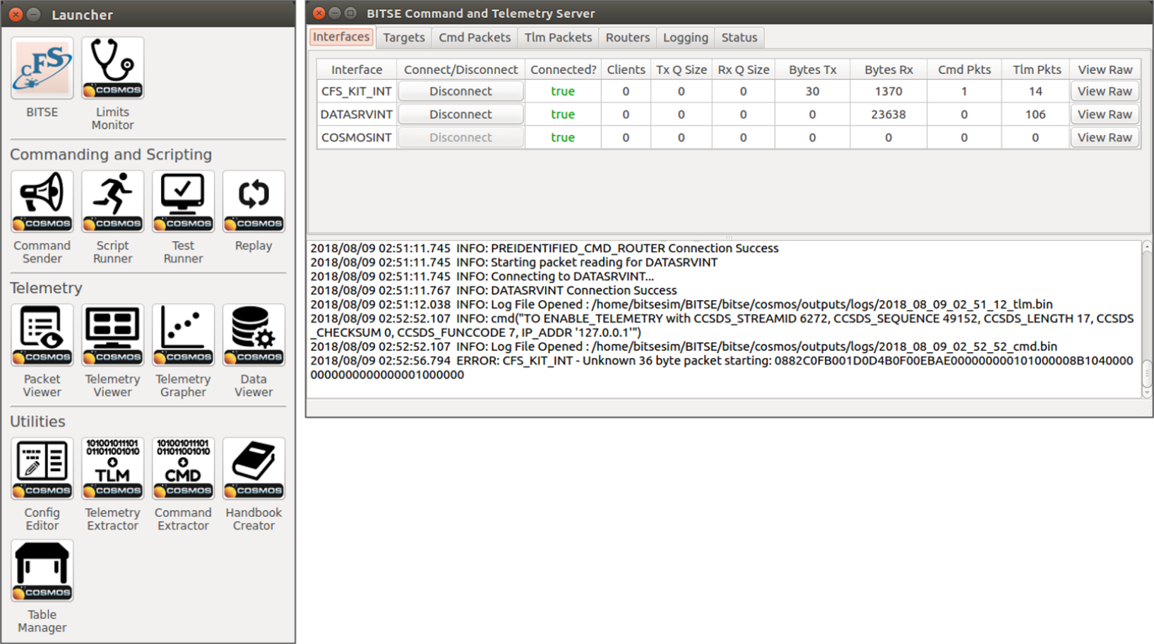
KASI led the development of the Ground Support Equiqment (GSE), Mission Operation Software and Data Processing Software of BITSE project, and used them to operate BITSE.
Mission Operation Software runs on the BITSE GSE, which sends commands for mission execution and receives and displays housekeeping information.
Mission Operation Software was developed with COSMOS.
COSMOS is a program developed by Ball Aerospace as a user interface for command and control of embedded systems.
COSMOS is used a lot for mission operations of balloon projects or satellite development projects conducted by NASA.
GSE and Mission Operation Software were used from the subsystem integration and test stages, such as camera T-VAC test, coronagraph integration test, communication test, and end-to-end test, and issue diagnosis and analysis were performed together at each stage.
In addition, during the observation of the high-altitude instrument, it played a key role in directly operating and communicating the observer on the ground, and the test of the high-altitude instrument was successfully completed.
The data processing software divides the raw data received from BITSE into 4-channel polarized data, stores it, and performs post processing (dark, flat). The image analysis software was used to analyze the polarization data in real time during observation and was run on a system independent of GSE.